Although radar has been employed for industrial level measurement for many years, the concept is still perceived by some as a new technology. In certain cases, this perception has limited radar’s uptake in applications where it may provide a clear advantage over existing technology. Here we consider how guided wave radar level measurement works, specification considerations, and where and when it provides a clear application advantage.
Bob Botwinski, senior global product manager for Guided Wave Radar (GWR) at Magnetrol International, says the fundamentals of guided wave radar level measurement come directly from Time Domain Reflectometry (TDR), a technology that has been employed for decades to find breaks in underground cables and in-wall cable installations in large buildings. TDR instruments launch low amplitude, high-frequency pulses onto the transmission line, cable, or waveguide under test, and then sequentially sample the reflected signal amplitudes.
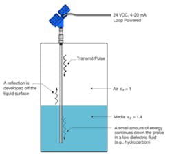
Fundamentals of Guided Wave Radar level measurement. (Courtesy Magnetrol International)
In a guided wave radar level measurement system, Botwinski says the waveguide is a probe immersed in the liquid (or dry, bulk media). The-high frequency electromagnetic pulses transmitted down the probe are reflected at the point of discontinuity between the air and the process medium. As with other "time of flight" instruments, those reflections are measured by high-speed circuitry in the transmitter, thus establishing the level measurement. The dielectric constant for typical process media can range from 1.4–100. The higher the dielectric constant of the medium being measured, the stronger the reflected signal is.
Interface Level Measurement: In industrial level measurement, Botwinski says interface is defined as the point between two immiscible liquids. When implementing guided wave radar level measurement in an interface application, a small reflection will be generated by the upper (lower dielectric) medium while most of the energy continues down the probe. Another, typically larger, reflection is generated by the lower (high dielectric) medium. A typical interface application would be oil over water, with the upper layer of oil being non-conductive (ε ≈ 2.0), and the lower layer of water being very conductive (ε ≈ 80).
Andreas Hessel, marketing manager for Rosemount Process Level products at Emerson Process Management, says GWR is a particularly good fit for some interface level measurements. "Because a proportion of the pulse will continue down the probe through low dielectric fluids, a second reflection (echo) can be detected from an interface between two liquids at a point below the initial liquid level," he says. "This characteristic makes GWR a good technology for measuring liquid/liquid interfaces such as oil and water and measuring through some foams."
Transmitter: Two-wire, 4-20mA, loop-powered GWR transmitters have come a long way since their introduction in 1998, says Botwinski. "They typically have accuracies of 0.1" (2.5 mm) or 0.1 percent of distance, whichever is greater, and have measurement ranges up to 200’," he says. "All modern industrial GWR transmitters carry explosion-proof, intrinsically safe and non-incendive (Div 2) approvals."
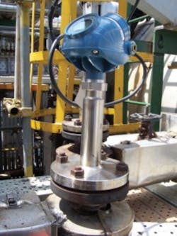
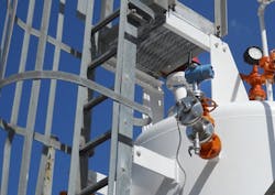
Guided wave radar level transmitter installed to provide level measurements and automated control. (Courtesy Emerson Process Management)
"Due to a wide variety of process conditions, choosing the proper probe (waveguide) is the most important aspect of successfully applying GWR," says Botwinski. Although most manufacturers have very broad probe offerings, all probe models are derived from three basic probe configurations: Coaxial, Twin Element, and Single Element"
Hessel says the key advantage of guided wave radar level measurement is that no compensation is necessary for changes in density, dielectric or conductivity of the fluid. Further, he says changes in pressure, temperature and most vapor space conditions have no impact on measurement accuracy; GWR is unaffected by high turbulence or vibrations; and build-up has practically no effect, meaning no need for re-calibration.
According to Emerson Process Management’s Andreas Hessel, there are several considerations end-users should make when specifying GWR technology, including:
Magnetrol’s Bob Botwinski offers the following recommendations to end-users who are considering GWR level measurement technology:
"There is no ideal level measurement technology," says Botwinski. "In a perfect world, all level measurement would be non-contact, perhaps even non-invasive." And while non-contact radar comes close to this in the simple, storagetype of application, Botwinski says it has significant weaknesses in more difficult, industrial process control applications. Those weaknesses can be overcome with the enhanced sensitivity GWR provides with focused energy down a waveguide. "That being said, these two radar technologies — contact and non-contact — form a formidable team in the effective level measurement of today’s industrial applications," says Botwinski.
Matt Migliore is the director of content for Flow Control magazine and FlowControlNetwork.com. He has covered technology and industry for 12-plus years.